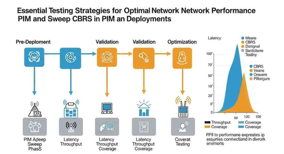
PIM and Sweep CBRS: Essential Testing Strategies for Optimal Network Performance
The Citizens Broadband Radio Service (CBRS) has revolutionized wireless communications by opening the 3.5 GHz band for shared spectrum use. However, deploying successful CBRS networks requires meticulous attention to signal quality and interference mitigation. This is where understanding PIM and sweep CBRS testing becomes crucial for network engineers and technicians.
Passive Intermodulation (PIM) and line sweep testing represent two fundamental measurement techniques that ensure CBRS deployments deliver optimal performance. These testing methodologies help identify potential sources of interference, verify system integrity, and maintain the high-quality standards demanded by modern wireless networks.
In this comprehensive guide, you’ll discover how to implement effective PIM testing and line sweep procedures for CBRS systems, understand the critical differences between these approaches, and learn about the equipment and best practices that drive successful deployments. Whether you’re troubleshooting existing installations or planning new CBRS networks, this article provides the technical insights needed to achieve superior performance.
Understanding PIM and Its Impact on CBRS Networks
Passive intermodulation represents one of the most significant challenges facing CBRS network deployments. This phenomenon occurs when two or more signals mix in passive components like connectors, cables, and antennas, creating unwanted spurious signals that can severely degrade network performance.
What is Passive Intermodulation (PIM)?
Passive intermodulation is the generation of additional frequencies when multiple carrier signals pass through nonlinear passive devices. Unlike active intermodulation, which occurs in amplifiers and other active components, PIM arises from nonlinearities in supposedly linear passive components. These nonlinearities can stem from loose connections, corroded contacts, contaminated surfaces, or manufacturing defects.
In CBRS networks operating in the 3.5 GHz band, PIM becomes particularly problematic because even small amounts of intermodulation can create interference that falls within the receive band. The third-order intermodulation products (IM3) are typically the most concerning, as they often fall closest to the original carrier frequencies.
PIM Sources and Their Impact on Network Performance
Understanding the primary sources of PIM in BTS systems is essential for effective troubleshooting and prevention. Common PIM sources include:
Connector Issues: Poorly installed or degraded RF connectors represent the most frequent source of PIM. Loose connections, improper torque specifications, and contamination can all contribute to nonlinear behavior. Even microscopic particles between connector surfaces can create PIM-generating junctions.
Cable Degradation: Coaxial cables, particularly older installations, can develop PIM over time due to moisture ingress, physical damage, or manufacturing defects. Water contamination in particular can create highly nonlinear conditions that generate significant PIM levels.
Antenna Feed Systems: Complex antenna feed networks with multiple combiners, splitters, and filters create numerous potential PIM sources. Each junction point represents a potential nonlinearity, and the cumulative effect can significantly impact system performance.
External Sources: Nearby metallic objects, including fence panels, guy wires, and even vegetation touching antenna elements, can create external PIM sources that are difficult to identify and eliminate.
The impact of PIM on CBRS network performance manifests in several ways. Elevated noise floors reduce receiver sensitivity, leading to decreased coverage areas and reduced data throughput. Call drop rates increase as the signal-to-noise ratio degrades, and network capacity suffers as interference levels rise. In severe cases, PIM can render portions of the spectrum unusable, effectively reducing the available bandwidth for CBRS operations.
Benefits of PIM Testing for LTE Networks
Implementing comprehensive PIM testing protocols delivers substantial benefits for CBRS and LTE network deployments. Proactive PIM testing identifies potential problems before they impact live traffic, reducing the likelihood of customer complaints and network outages. Early detection of PIM sources allows for targeted repairs that minimize downtime and maintenance costs.
PIM testing also enables network optimization by identifying the cleanest frequency channels for deployment. This information proves invaluable when planning channel assignments and power levels, particularly in dense urban environments where interference sources are abundant.
From a regulatory compliance perspective, PIM testing helps ensure that CBRS deployments meet the stringent interference requirements mandated by the FCC. The shared nature of CBRS spectrum makes interference mitigation critical for protecting incumbent users and maintaining harmonious spectrum sharing.
The Role of Line Sweep Testing in CBRS Deployments
Line sweep testing complements PIM measurements by providing comprehensive analysis of transmission line characteristics. This testing methodology evaluates critical parameters including VSWR measurement, insertion loss analysis, and return loss testing across the entire frequency range of interest.
Why Perform Line Sweep Testing?
Line sweep testing serves multiple critical functions in CBRS network deployments. First, it verifies impedance matching throughout the RF path, ensuring maximum power transfer and minimizing reflections that can degrade performance. Poor impedance matching not only reduces radiated power but can also create standing wave patterns that increase component stress and reduce reliability.
Second, line sweep testing identifies cable and connector problems that might not generate obvious PIM signatures. Small discontinuities in impedance can create reflections that, while not immediately problematic, may contribute to system instability or reduced performance margins.
Distance-to-fault diagnostics represent another crucial capability of line sweep testing. When problems are detected, advanced sweep instruments can precisely locate the fault along the transmission line, dramatically reducing troubleshooting time and enabling targeted repairs.
How Line Sweep Improves PIM Test Accuracy
The relationship between line sweep and PIM testing is synergistic rather than competitive. Line sweep testing identifies impedance discontinuities and reflection points that may contribute to PIM generation. By ensuring optimal impedance matching and minimal reflections, line sweep testing creates conditions that maximize PIM test accuracy and reliability.
Standing wave patterns created by impedance mismatches can mask or amplify PIM signatures, leading to inconsistent test results. By first performing comprehensive line sweep measurements and correcting any identified issues, technicians can achieve more reliable and repeatable PIM test results.
Additionally, line sweep testing helps distinguish between reflective and non-reflective PIM sources. Reflective PIM sources, such as loose connectors, typically exhibit both impedance discontinuities and PIM generation. Non-reflective sources, like contaminated surfaces, may generate PIM without significant impedance changes. Understanding this distinction helps guide troubleshooting efforts and repair strategies.
Line Sweep vs. PIM Testing: Understanding the Differences

While both line sweep and PIM testing evaluate RF system performance, they measure fundamentally different characteristics and serve complementary roles in comprehensive system validation.
Technical Differences and Applications
Line sweep testing measures linear characteristics of the RF path, including frequency response, impedance variations, and reflection coefficients. These measurements are performed using single-tone stimuli and analyze how the system responds across the frequency range of interest. The primary metrics include VSWR, return loss, insertion loss, and distance-to-fault information.
PIM testing, conversely, evaluates nonlinear characteristics by applying multiple high-power test tones and measuring the resulting intermodulation products. This testing specifically targets the passive nonlinearities that create interference in multi-carrier systems. PIM testing typically focuses on third and fifth-order intermodulation products, with measurements expressed in dBc (decibels relative to carrier) or absolute power levels.
The frequency domain also differs between these test types. Line sweep testing can cover broad frequency ranges, often spanning multiple octaves, while PIM testing focuses on specific frequency combinations relevant to the planned carrier deployment. CBRS PIM testing typically uses test frequencies that will generate intermodulation products within the 3.5 GHz receive band.
Complementary Nature of Both Testing Methods
Rather than viewing line sweep and PIM testing as alternatives, successful CBRS deployments employ both methodologies in a coordinated testing strategy. Line sweep testing typically precedes PIM testing, ensuring optimal system conditions before applying high-power multi-tone signals.
This sequence prevents potentially misleading PIM test results that might occur in systems with significant impedance mismatches or cable faults. By first optimizing the linear characteristics of the system, technicians can focus PIM testing efforts on identifying genuine nonlinear sources rather than artifacts created by poor system conditions.
The combination also provides comprehensive fault localization capabilities. Line sweep testing can quickly identify the general location of problems along the transmission path, while PIM testing can confirm whether these locations also represent sources of intermodulation interference.
Distance-to-PIM Measurement Techniques
Advanced PIM testing capabilities now include distance-to-PIM measurement, which represents a significant advancement in troubleshooting efficiency. This technology combines traditional PIM measurement techniques with time domain analysis to locate PIM sources along the transmission path.
Technical Implementation
Distance-to-PIM measurement relies on analyzing the time delay between transmitted test signals and received intermodulation products. By correlating the phase relationships of multiple intermodulation products, sophisticated algorithms can calculate the distance to PIM sources with remarkable accuracy.
The measurement process begins with traditional PIM testing to establish baseline intermodulation levels. The test instrument then analyzes the phase relationships between different intermodulation products, looking for patterns that indicate specific propagation delays. Advanced signal processing techniques extract distance information from these phase measurements.
Accuracy depends on several factors, including the frequency separation of test tones, the quality of phase measurements, and the characteristics of the transmission line under test. Typical systems can locate PIM sources within a few feet, dramatically reducing the time required for fault isolation and repair.
Practical Applications and Limitations
Distance-to-PIM measurement proves particularly valuable in complex antenna feed systems where multiple potential PIM sources exist. Rather than systematically disconnecting components to isolate problems, technicians can quickly identify the specific location requiring attention.
However, this technology has limitations that users must understand. Multiple PIM sources can create complex interference patterns that complicate distance calculations. Very weak PIM sources may not provide sufficient signal levels for accurate distance measurement. Additionally, the technique assumes that PIM sources behave as discrete point sources, which may not always reflect reality.
Despite these limitations, distance-to-PIM measurement represents a powerful troubleshooting tool that significantly improves maintenance efficiency and reduces system downtime.
Key Equipment and Best Practices
Selecting appropriate test equipment is crucial for successful PIM and sweep CBRS testing. The market offers various solutions, each with specific capabilities and limitations that must be understood for optimal results.
Choosing the Best PIM analyzer for Cellular Base Stations
When evaluating PIM analyzers for CBRS applications, several key specifications demand attention. Power output capability directly affects the sensitivity and reliability of PIM measurements. Higher power levels generally provide better measurement sensitivity but may also stress system components and potentially create safety hazards.
Frequency coverage must encompass the specific CBRS bands of interest, with particular attention to test frequency combinations that generate intermodulation products within receive bands. Dynamic range specifications determine the ability to detect low-level PIM products in the presence of high-power test signals.
Anritsu PIM Master MW82119B represents a leading solution specifically designed for cellular base station testing. This instrument combines high-power PIM testing with comprehensive line sweep capabilities, providing a complete solution for CBRS system validation.
Key features of the MW82119B include dual-source PIM testing with power levels up to +43 dBm, frequency coverage spanning 350 MHz to 5.8 GHz, and integrated distance-to-PIM capability. The instrument also incorporates advanced line sweep functionality with full two-port vector network analysis capabilities.
Anritsu PIM analyzer Price and Value Proposition
Investment in quality PIM testing equipment requires careful consideration of both initial costs and long-term value. While the Anritsu PIM Master MW82119B represents a significant investment, the comprehensive capabilities and measurement accuracy often justify the cost through improved troubleshooting efficiency and reduced maintenance expenses.
Factors affecting pricing include frequency coverage, power output levels, measurement accuracy specifications, and additional features like distance-to-PIM capability. Organizations should evaluate total cost of ownership, including training requirements, calibration costs, and ongoing support expenses.
Leasing and rental options provide alternatives for organizations with limited budgets or occasional testing requirements. These arrangements can provide access to current technology without the full capital investment.
Troubleshooting PIM in Antenna Feed Lines
Effective PIM troubleshooting requires systematic approaches that maximize efficiency while minimizing system disruption. The process typically begins with baseline PIM measurements to establish the severity and characteristics of the problem.
Initial Assessment: Comprehensive PIM testing across all relevant frequency combinations provides baseline data and identifies the most problematic intermodulation products. Comparing results against system specifications helps prioritize repair efforts.
Visual Inspection: Physical examination of RF connections, cables, and antenna elements often reveals obvious problems like loose connectors, corrosion, or physical damage. This step should precede more complex testing procedures.
Systematic Isolation: When multiple potential PIM sources exist, systematic disconnection and reconnection of system elements helps isolate specific problem areas. This process requires careful documentation to ensure proper system restoration.
Distance-to-PIM Analysis: When available, distance-to-PIM measurement can dramatically reduce troubleshooting time by pinpointing specific fault locations. This capability proves particularly valuable in complex multi-element antenna systems.
Verification Testing: After completing repairs, comprehensive retesting ensures that problems have been resolved and that no new issues have been introduced during the repair process.

BTS System Testing Integration
Modern BTS system testing requires integration of PIM and line sweep measurements with broader system validation procedures. This integration ensures that RF performance optimization aligns with overall system requirements and operational constraints.
Testing schedules should coordinate PIM and line sweep measurements with other maintenance activities to minimize system downtime. Automated testing capabilities can perform routine measurements during low-traffic periods, providing ongoing system health monitoring.
Documentation standards should capture both measurement results and system configuration details, enabling trend analysis and predictive maintenance strategies. This information proves valuable for optimizing maintenance schedules and identifying systematic problems.
Anritsu Testing Solutions and Equipment Overview
Anritsu has established itself as a leading provider of RF test equipment for cellular and wireless communications applications. Their comprehensive portfolio includes specialized solutions for PIM testing, line sweep analysis, and integrated BTS system testing.
Anritsu PIM Master Overview
The PIM Master family represents Anritsu’s flagship solution for passive intermodulation testing. These instruments combine high-power signal generation with sensitive receiver capabilities, enabling detection of even very low-level intermodulation products.
Current PIM Master models offer several key advantages over competitive solutions. Integrated distance-to-PIM capability eliminates the need for separate instruments, reducing equipment costs and simplifying field operations. Advanced signal processing algorithms provide improved measurement accuracy and repeatability.
User interface design emphasizes operational efficiency, with intuitive menus and automated test sequences that minimize operator errors. Built-in help systems and measurement wizards guide users through complex procedures, reducing training requirements and improving productivity.
Anritsu Line Sweep Tools LST
Anritsu’s line sweep tools complement PIM testing capabilities with comprehensive transmission line analysis. These solutions provide vector network analysis capabilities optimized for field testing applications, combining measurement accuracy with rugged field-ready construction.
Integration between line sweep and PIM testing functions enables coordinated testing strategies that maximize troubleshooting efficiency. Shared display and analysis capabilities allow technicians to correlate impedance measurements with PIM test results, providing deeper insights into system behavior.
Advanced features include automated cable loss compensation, which ensures accurate measurements regardless of test setup variations. Time domain analysis capabilities enable precise fault location, while frequency domain measurements provide comprehensive system characterization.
Anritsu BTS Testing Solutions
Beyond specialized PIM and line sweep instruments, Anritsu offers comprehensive BTS testing solutions that address the full range of cellular base station validation requirements. These solutions integrate RF testing with protocol analysis, providing complete system validation capabilities.
Modular instrument architectures enable customized configurations that match specific testing requirements and budget constraints. Software-defined capabilities allow instruments to adapt to evolving technology requirements without hardware changes.
Remote operation capabilities enable centralized testing coordination and automated measurement sequences. These features prove particularly valuable for large-scale deployments where consistency and efficiency are paramount.
Case Studies and Real-Life Examples
Understanding how PIM and sweep CBRS testing applies in real-world scenarios provides valuable insights into best practices and potential challenges. The following examples illustrate common situations and their solutions.
Urban CBRS Deployment Case Study
A major metropolitan area CBRS deployment experienced significant interference issues shortly after activation. Initial customer complaints centered on reduced data rates and frequent call drops in specific coverage areas. Network performance monitoring revealed elevated noise floors and reduced signal-to-noise ratios in the affected sectors.
Initial troubleshooting efforts focused on potential external interference sources, including other CBRS operators and incumbent radar systems. However, interference characteristics suggested internal system problems rather than external sources.
Comprehensive PIM testing using the Anritsu PIM Master MW82119B revealed severe intermodulation distortion in several antenna feed systems. PIM levels exceeded -100 dBc, well above acceptable thresholds for reliable operation. Distance-to-PIM analysis pinpointed specific connector locations as primary sources of interference.
Detailed inspection of the identified connectors revealed improper installation techniques and contamination from construction activities. Several connectors showed evidence of inadequate torque application, while others contained visible debris and moisture.
Systematic connector replacement and proper installation procedures reduced PIM levels to acceptable ranges, typically below -150 dBc. Follow-up testing confirmed elimination of interference issues, and network performance returned to design specifications.
Rural CBRS Implementation Example
A rural CBRS deployment faced unique challenges related to harsh environmental conditions and limited maintenance access. The installation utilized existing tower infrastructure with extensive coaxial cable runs and multiple antenna positions.
Pre-deployment line sweep testing revealed several impedance discontinuities along transmission paths, indicating potential connector problems or cable damage. VSWR measurements exceeded 1.5:1 at several frequencies within the CBRS band, suggesting significant reflection issues.
Systematic analysis using time domain techniques located specific fault positions along the transmission lines. Physical inspection revealed water intrusion in several outdoor connectors and corrosion damage in older cable sections.
Preventive maintenance procedures included complete connector replacement with improved weatherproofing techniques and cable section replacement where corrosion was evident. Post-repair testing confirmed VSWR improvements to better than 1.2:1 across the operating band.
PIM testing following the line sweep improvements showed excellent results, with intermodulation levels well below specification limits. The combination of improved impedance matching and reduced connector problems created optimal conditions for long-term reliable operation.
Complex Multi-Operator Environment
A shared CBRS installation supporting multiple operators presented unique testing challenges due to the complex antenna feed system and coordination requirements between different service providers.
The system utilized sophisticated combiners and filtering networks to enable spectrum sharing while maintaining isolation between operators. This complexity created multiple potential PIM sources and made traditional troubleshooting approaches impractical.
Comprehensive testing strategies required coordination between operators to schedule measurement windows that wouldn’t disrupt active services. Advanced test procedures utilized swept frequency PIM testing to identify frequency-dependent intermodulation characteristics.
Results revealed that PIM generation varied significantly with frequency, indicating that some intermodulation sources were frequency-selective. Distance-to-PIM analysis identified multiple sources at different points in the feed system, requiring prioritized repair strategies.
Systematic repairs addressed the most severe PIM sources first, with ongoing monitoring to ensure that changes in one part of the system didn’t create problems elsewhere. The complex nature of the installation required iterative testing and optimization cycles to achieve acceptable performance levels.
Frequently Asked Questions and Common Challenges

How to Perform PIM Testing on BTS Systems
Performing effective PIM testing on BTS systems requires careful attention to test procedures, safety considerations, and result interpretation. The following guidelines ensure reliable and repeatable measurements.
Safety Considerations: PIM testing utilizes high-power RF signals that can pose safety hazards to personnel and equipment. Ensure that all personnel are clear of antenna near-field regions during testing. Verify that sensitive electronic equipment is protected from RF exposure.
System Preparation: Before beginning PIM testing, perform complete system shutdown of active transmitters. Verify that all RF paths are properly terminated and that test equipment is correctly connected. Document system configuration to ensure proper restoration after testing.
Test Frequency Selection: Choose test frequencies that will generate intermodulation products within the receive bands of interest. For CBRS applications, this typically involves frequencies that create third-order products in the 3.55-3.7 GHz range.
Power Level Optimization: Use sufficient power levels to ensure adequate measurement sensitivity while avoiding component damage. Start with moderate power levels and increase gradually while monitoring for any signs of component stress.
Measurement Interpretation: Understand that PIM measurements represent worst-case conditions and may not directly correlate with operational performance under lower power conditions. Use measurement results to guide repair priorities rather than absolute performance predictions.
Line Sweep Tool Comparison: Anritsu vs. Competitors
The market for line sweep testing equipment includes several major manufacturers, each offering solutions with different capabilities and price points. Understanding these differences helps guide equipment selection decisions.
Frequency Coverage: Anritsu solutions typically provide broad frequency coverage that spans multiple cellular bands, while some competitors focus on specific frequency ranges. Consider future expansion plans when evaluating frequency coverage requirements.
Measurement Accuracy: All major manufacturers meet basic accuracy requirements for cellular applications, but subtle differences in calibration procedures and measurement algorithms can affect results. Evaluate specifications carefully and consider real-world performance requirements.
Integration Capabilities: Anritsu’s strength lies in integrated solutions that combine line sweep and PIM testing in single instruments. This integration can reduce equipment costs and simplify field operations, particularly for organizations performing both types of testing regularly.
User Interface and Ease of Use: Different manufacturers emphasize different aspects of user interface design. Some prioritize measurement speed, while others focus on comprehensive analysis capabilities. Consider operator skill levels and training requirements when making comparisons.
Support and Service: Long-term support considerations include calibration services, repair capabilities, and technical support quality. These factors can significantly impact total cost of ownership and operational efficiency.
Distance-to-PIM Measurement Kit Requirements
Implementing distance-to-PIM measurement capabilities requires specific equipment configurations and setup procedures. Understanding these requirements helps ensure successful deployment and reliable results.
Instrument Capabilities: Distance-to-PIM measurement requires advanced signal processing capabilities and precise phase measurement systems. Not all PIM analyzers include this functionality, so verify capabilities before making purchasing decisions.
Calibration Requirements: Accurate distance measurements depend on precise calibration procedures that account for cable delays and instrument characteristics. Ensure that calibration standards and procedures are appropriate for the intended measurement accuracy.
Test Setup Considerations: Physical test setup affects measurement accuracy, particularly cable selection and connection procedures. Use high-quality test cables with known characteristics, and minimize setup variations between measurements.
Environmental Factors: Temperature variations and mechanical vibrations can affect measurement accuracy. Consider environmental conditions when establishing measurement procedures and interpreting results.
Common PIM Testing Mistakes and How to Avoid Them
Experience has identified several common mistakes that can compromise PIM testing accuracy and reliability. Understanding these pitfalls helps ensure consistent results and avoid wasted troubleshooting efforts.
Inadequate System Preparation: Failing to properly shut down active transmitters or leaving unterminated connections can create false PIM indications. Always verify complete system shutdown and proper termination before beginning testing.
Inappropriate Test Frequencies: Using test frequencies that don’t create intermodulation products in the bands of interest renders testing ineffective. Carefully calculate test frequency combinations to ensure relevant results.
Insufficient Power Levels: Low test power levels may not provide adequate sensitivity to detect marginally acceptable PIM sources. However, excessive power can damage components or create safety hazards. Find the appropriate balance for your specific application.
Poor Connection Practices: Contaminated or improperly installed test connections can create PIM sources that mask system problems. Use clean, properly torqued connections and high-quality test cables.
Misinterpreting Results: PIM measurements can be influenced by many factors, including standing waves, connector reflections, and environmental conditions. Understand measurement limitations and consider multiple data points when drawing conclusions.
Industry Standards and Compliance Requirements
CBRS deployments must comply with various industry standards and regulatory requirements that address interference management and system performance. Understanding these requirements helps guide testing strategies and acceptance criteria.
FCC Requirements for CBRS Operations
The Federal Communications Commission has established specific requirements for CBRS operations that directly impact PIM and line sweep testing strategies. These requirements address both technical performance and interference protection obligations.
Interference Protection: CBRS operators must protect incumbent users, including federal radar systems and fixed satellite services. This protection extends beyond fundamental signal emissions to include intermodulation products that might interfere with incumbent operations.
Spurious Emission Limits: Technical rules specify maximum allowable spurious emission levels, including intermodulation products generated by passive components. PIM testing helps ensure compliance with these limits and identifies potential problems before they impact operations.
Coordination Requirements: In areas where incumbent protection is required, CBRS operators must coordinate with the Spectrum Access System (SAS) to ensure interference-free operation. Comprehensive PIM testing supports these coordination efforts by demonstrating system cleanliness.
Industry Testing Standards
Several industry organizations have developed standards that address PIM testing procedures and acceptance criteria. These standards provide guidance for measurement techniques, equipment specifications, and result interpretation.
ANSI/TIA Standards: The Telecommunications Industry Association has published standards that address PIM testing procedures for cellular base stations. These documents provide detailed guidance on test procedures, frequency selection, and acceptance criteria.
IEC International Standards: International Electrotechnical Commission standards address broader aspects of RF testing, including safety requirements and measurement uncertainty considerations. These standards help ensure consistent testing practices across different organizations and geographic regions.
3GPP Technical Specifications: The 3rd Generation Partnership Project includes PIM-related requirements in various technical specifications for LTE and 5G systems. Understanding these requirements helps ensure that testing strategies align with system design objectives.
Future Trends and Technology Evolution
The evolution of wireless communications technology continues to drive new requirements for PIM and line sweep testing. Understanding these trends helps organizations prepare for future challenges and opportunities.
5G and Advanced Antenna Systems
The deployment of 5G networks brings new challenges for PIM and line sweep testing, particularly related to advanced antenna systems and higher frequency operations. Massive MIMO systems create complex RF environments with multiple signal paths and potential interference sources.
Beamforming Complications: Advanced beamforming systems create dynamic RF environments where traditional testing approaches may not fully characterize system performance. New testing methodologies must account for the time-varying nature of beamformed signals.
Higher Frequency Operations: 5G deployments in millimeter wave bands present unique challenges for PIM testing, including increased path loss and atmospheric absorption effects. Test equipment must evolve to address these new frequency ranges while maintaining measurement accuracy.
Integrated Antenna Systems: The trend toward integrated antenna and radio systems complicates traditional testing approaches that assume discrete components. New testing strategies must adapt to these integrated architectures.
Software-Defined Testing Solutions
The evolution toward software-defined radio architectures is driving corresponding changes in test equipment design. Software-defined test solutions offer flexibility and adaptability that traditional fixed-function instruments cannot match.
Adaptive Test Procedures: Software-defined instruments can modify test procedures based on initial measurement results, optimizing testing efficiency and accuracy. These adaptive capabilities reduce testing time while improving result reliability.
Remote Operation Capabilities: Advanced software architectures enable remote operation and automated testing sequences that reduce the need for on-site technical personnel. These capabilities prove particularly valuable for large-scale deployments and ongoing maintenance operations.
Machine Learning Integration: Artificial intelligence and machine learning techniques are beginning to influence test equipment design, enabling automated fault diagnosis and predictive maintenance capabilities.
Conclusion
PIM and sweep CBRS testing represents a critical foundation for successful wireless network deployments in the shared spectrum environment. The combination of comprehensive PIM testing and detailed line sweep analysis provides the technical insights necessary to ensure optimal system performance while meeting regulatory compliance requirements.
The synergistic relationship between these testing methodologies enables more effective troubleshooting and system optimization than either approach alone. Line sweep testing creates optimal conditions for accurate PIM measurements while providing valuable diagnostic information about transmission line characteristics. PIM testing identifies the nonlinear sources that can severely impact multi-carrier system performance.
Success in CBRS deployments requires understanding both the technical aspects of these testing methodologies and their practical implementation challenges. Equipment selection, test procedure development, and result interpretation all demand careful attention to detail and thorough understanding of underlying principles.
The investment in quality test equipment and comprehensive testing procedures pays dividends through improved system reliability, reduced maintenance costs, and enhanced customer satisfaction. Organizations that prioritize thorough PIM and line sweep testing position themselves for success in the competitive CBRS marketplace.
As wireless technology continues to evolve toward 5G and beyond, the importance of comprehensive RF testing will only increase. The principles and practices outlined in this guide provide a solid foundation for addressing current challenges while preparing for future technological developments.
Ready to optimize your CBRS network performance? Contact our technical experts today to discuss your specific PIM and line sweep testing requirements. Whether you need equipment recommendations, training programs, or comprehensive testing services, we’re here to help you achieve superior network performance. Share this article with your colleagues and join the conversation about CBRS testing best practices in the comments below.